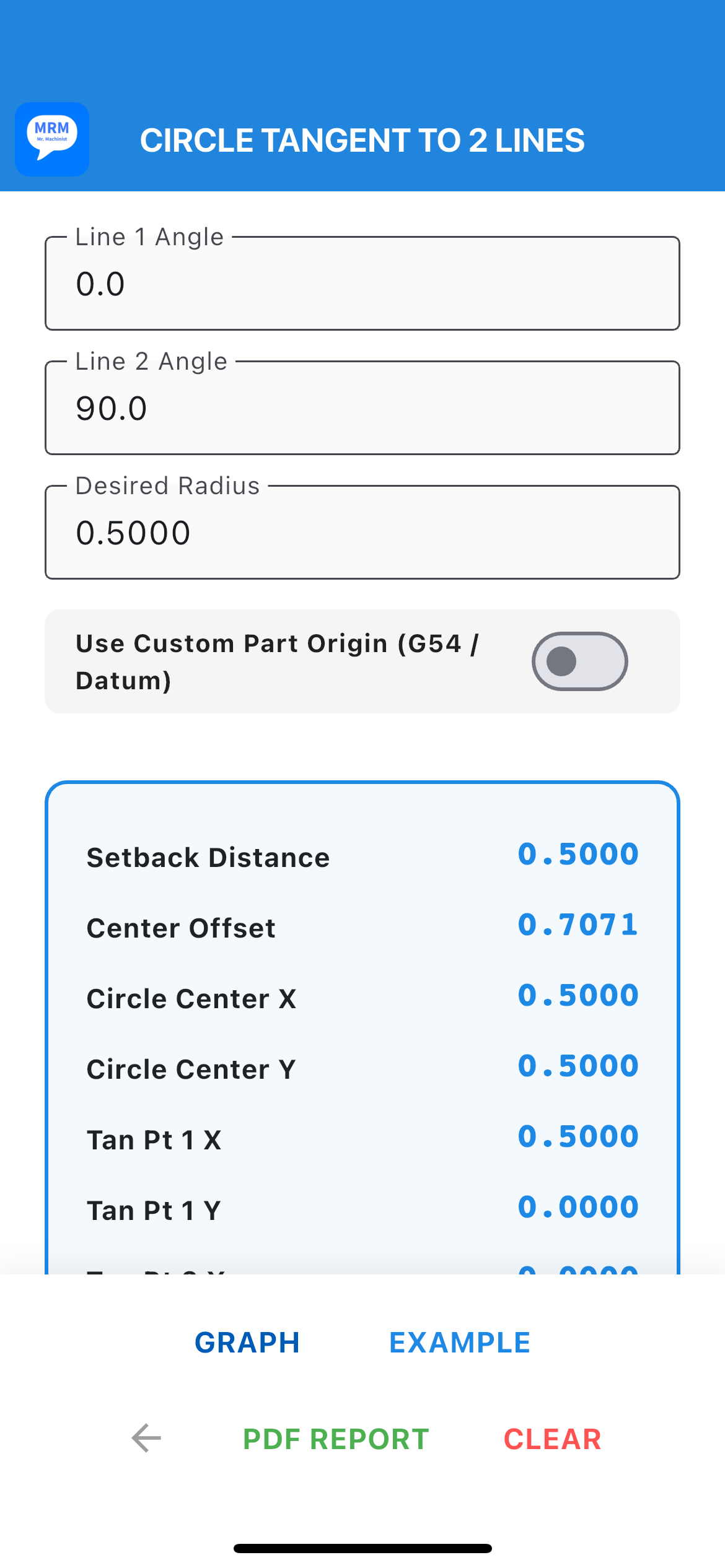
Live Layout Workspace: Circle Tangent to 2 Lines Module
Circle Tangent to 2 Lines Help
This utility calculates the exact layout points, setback distances, and center locations required to blend a radius smoothly (tangently) into a corner formed by two intersecting lines.
Stuck without a blueprint or want to see how this function behaves before running a part? Tap the EXAMPLE button at the bottom of the screen.
- Overwrite Protection: If you have already started typing numbers into the inputs, the app will instantly pop up a safety dialog warning you that your workspace is about to change. You can cancel to protect your data or proceed to load the benchmark dataset.
- Instant Baseline: It automatically populates the fields with a standard 90° perpendicular corner and a 0.5000" blend radius.
- Live Answers: It immediately runs the math engines so you can see how input angles generate precise setback depths down to the 4th decimal place.
- Datum Simulation: Flip the "Use Custom Part Origin" switch and hit EXAMPLE again. It instantly injects absolute G54 coordinates, showing you exactly how raw geometry shifts into absolute machine code.
- Visual Link: Once the example values are loaded, you can immediately tap the GRAPH button to see a live blueprint representation of that exact setup. It acts like a mini-classroom directly on the shop floor!
Need a physical layout sheet for the setup man or an inspection report for quality records? Tap the PDF REPORT button (available as soon as a calculation is active).
- Ink-Saving Design: While the mobile app uses a high-contrast dark theme, the PDF automatically strips out the dark canvas, printing the vector schematic in dark charcoal and blue lines on a pure white background to save expensive printer ink.
- Shop Floor Docs: The report beautifully maps out every baseline input, active statuses (G54 vs Local), the calculated tool path coordinates, and a scalable blueprint vector graphic right in the center.
- Native Sharing & Printing: Tapping the button launches your mobile device's system tray, allowing you to instantly print wirelessly to a shop printer, text a screenshot to a coworker, or save it to your cloud drive.
The theoretical sharp corner where the two lines intersect. In many blueprints, this point sits out in empty space.
The linear distance from the sharp vertex back along each line to the exact point where the straight line ends and the radius begins (Tangent Points 1 & 2).
The direct distance from the sharp vertex, moving along the angle's centerline (bisector), straight to the physical center point of the radius.
1. Standard Geometry Mode (Switch OFF)
Triggers raw geometric calculations. The intersection vertex is treated as the origin (0, 0).
• Useful for quick reference, drafting, or manual layout where you are measuring directly from the physical corner of a part.
2. Custom Part Origin / Work Datum Mode (Switch ON)
Unlocks absolute coordinate shifting. You input the X and Y coordinates of the vertex relative to your true part datum (G54 or print origin).
• Useful for CNC Programming (G-code) or CMM inspection. It eliminates manual pad-and-pencil math by instantly converting geometric distances into absolute machine coordinates.
Imagine you are programming a tool path to mill a corner where a vertical edge (90°) meets an angled profile (30°), and you need to blend them smoothly with a 0.250 inch radius.
• Line 1 Angle: 90
• Line 2 Angle: 30
• Desired Radius: 0.250
• Use Custom Part Origin: [ON]
• Vertex X Offset: -2.250
• Vertex Y Offset: -5.000
• Upper Right Corner: 180 & 90
• Upper Left Corner: 0 & 90
• Lower Left Corner: -90 & 0
• Lower Right Corner: -90 & -180
• Setback Distance: How far to back away from the corner on each line to locate the blend start and end points.
• Circle Center X & Y: The absolute coordinates you need to type into your G-code block to position the tool path.
• Tan Pt 1 & 2 X & Y: The exact touchpoints where your linear interpolation transitions into an arc.
When you tap the GRAPH button, the canvas draws a digital schematic of your geometry.
- Pinned at the top is your master readout block for easy verification.
- On the layout canvas, the blue outline represents the tangent circle body.
- The red indicators marked "1" and "2" show the precise physical location of Tangent Point 1 and Tangent Point 2 relative to your origin benchmark.